您现在的位置是:主页 > 基础 > 其他基础电路图 >
汽车热限制器的烙铁AutoHeatLimiterforSolderingIron-其他基础电路图
发布时间:2023-03-17 09:09:34所属栏目:其他基础电路图 已帮助人编辑作者:电路图知识网
汽车热限制器的烙铁 Auto Heat Limiter for Soldering Iron
Wattage of load
10W
18W
25W
35W
65W
80W
Value of R5 (in ohms)
330
180
136 (68+68)
100
56
44 (22+22)
Wattage of R5 (in watts)
01
02
02
04
05
6.5
Usually a soldering iron takes a couple of minutes to get adequately heated up to melt the solder, after which the heat generated is much above the requirement and is wasted. Moreover, excessive heat decreases the life of the bit and the element, causing serious damage to the components.
The above circuit solves this problem in a simple and inexpensive way and could be used to various types of loads up to 80watts.
How it works
Once the main is switched on, an approximate 15v drop of the positive half cycle across R5 is detected and supplied to Q1 (SL100 or D313), which acts as a voltage regulator. Zener diode D2 together with diode D3 (yellow LED) stabilizes the emitter voltage of Q1 at 13.2Vdc, which is then delivered to the relay circuit built around Q2 and C3. Capacitor C3 charges through the base-emitter path of Q2 and causes the relay to actuate, which in turn allows both the half cycles of the AC mains to flow through diode D6 and R5 to the load to heat it up at a normal rate.
After a certain lapse of time (about 2 minutes preset) C3 saturates and Q2 stops conducting through the relay, thus switching on series diode D5 to allow only half of the Ac cycle through the load.
After switching off the system, C3 discharges very slowly through R2 and R3. Before C3 gets completely discharged, if the power is switched on again, C3 takes a shorter time to reach the saturation level, thus switching series diode D5 much earlier than the preset time to prevent double heating of the load.
However, if the circuit is switched on only after a few seconds of switching off, C3 gets no time to discharge and the relay does not actuate at all. Moreover, if the relay circuit fails due to any reason and Q2 does not conduct, no harm is done to the load because in that case D5 remains in series with it. Thus the circuit offers complete protection to the load.
As stated earlier, the given value of C3 gives a delay of 2 minutes. However, a 1000mfd capacitor can also be used to produce a 4.5-minute delay. R5 maintains a drop of about 15V across itself. So for use in different load conditions its value changes as shown in Table 1.
The whole circuit can be mounted on a PCB and fitted in an adapter case (7.6cm X 5.1cm X 6.4cm) and used as a mains plug. Since R5 gets heated up during the operation, it should be kept well isolated from the other components.
Components List
R1 - 220 ohms
R2 10K
R3 150K
R4 82K
(all resistors should be 5% close tolerance)
C1- 100 uf, 25V dc working electrolytic
C2 100 uf, 25V dc working electrolytic
C3 220 uf, 16V dc working electrolytic
(advisable to use close tolerance Caps. to obtain correct timings)
D1, D4, D5, D6 IN4007
D2 12V 400mw, Zener diode
D3 Yellow LED
RLY1 6V, 300 ohms DC relay
Q1 SL100 or D313
Q2 BC108
Tags:
相关文章
猜你喜欢

可控硅与场效应管及三极管的区别-其他基础电路图
可控硅与场效应管及三极管的区别 1.场效应管的源极s、栅极g、漏极d分别对应...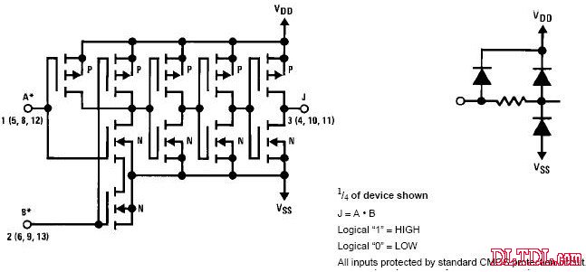
CD4071 CD4081中文资料_CD4071功能引脚图_CD4081应用电路图-其他基础电路图
CD4071 四2输入端或门OR NSC/TI CD4081 四2输入端与门AND NSC/HIT/TI CD4071真值表:Y=A+B...
采用RS触发器的防抖电路-其他基础电路图
所示为采用RS触发器的防抖动电路。由图可 知,在开关的触点部位加了RC积分电...
由T触发器组成的非同步即使输球电路及其信号波形-其他基础电路图
所示是利用T触发器组成的计数器电路及其信号波形,它是一种非同步式计数器...

其他基础电路图相关资讯
供电耦合器一晶闸管的接口电路a-其他基础电路图
-
提高功率因数的方法-其他基础电路图
LM7824A中文资料-其他基础电路图
晶振负载电容的计算-其他基础电路图
稳压用运算放大器基本电-其他基础电路图
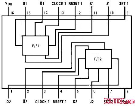
CD4027中文资料-其他基础电路图
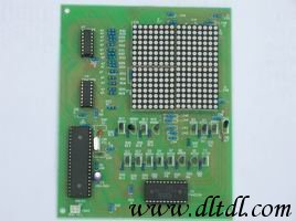
经典实用的单片机模块电路设计_单片机电路图-其他基础电路图
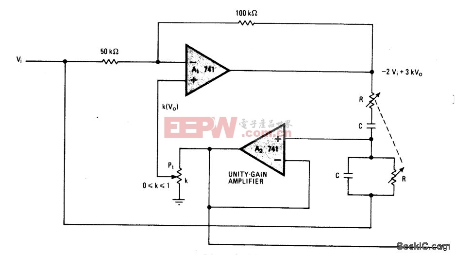
可选择带宽的NOTCH滤波器-其他基础电路图
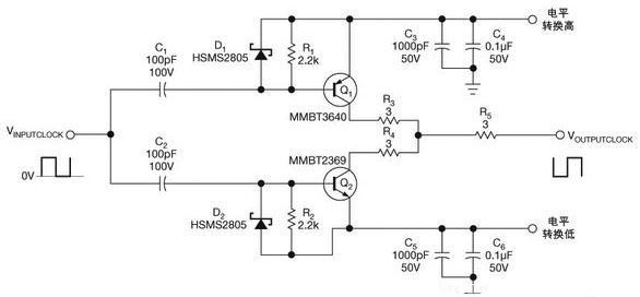
简易电平转换电路图-其他基础电路图
多路脉冲编码器-其他基础电路图
超高频射频识别标签灵敏度的测试方法及解决方案-其他基础电路图
-
电阻器好坏的判断与检测-其他基础电路图

焊锡技术-教你怎样使焊锡点光亮-其他基础电路图
具有75欧同辅导线的阻抗-其他基础电路图
采用CMOS或非门的防抖动电路-其他基础电路图