您现在的位置是:主页 > 基础 > 其他基础电路图 >
最好的电子开关-其他基础电路图
发布时间:2022-12-06 10:55:23所属栏目:其他基础电路图 已帮助人编辑作者:电路图知识网
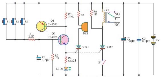
此开关电路,它可以是有用的许多things.which可以被控制电路的一个输出铃或其它声源电路或控制继电器或SCR(RY1,和SCR2的电路,仅用于与交流电压源)触点开关(S1,S2和S3)在并联电路中,它被用于控制连接的开关电路,可以有效的两个晶体管的工作是高度不确定的交换机,并做防盗报警器电路或控制报警信号。不会触发错误,因为没有其他的局部噪声传导的SCR2的时间是非常稳定,因为电阻1K作为触发relay.When平行和按下开关S2,它通常是关闭的用于断路器。继电器停止工作。LED1访问的晶体管Q2的发射极引脚,指示灯会亮,当电路工作原理。
This switches circuit,It can be useful many things.which a output of the circuit can be controlled a bell or other sound source circuit or control relay or SCR.(a circuit for RY1,and SCR2 are used with AC voltage source only) The contact switches (S1, S2 and S3) in the parallel circuit,it were used to control a connect switched circuit, which can usefully for a burglar alarm circuit or control alarm signal.
The two transistors work as switches that are highly uncertain,and do not trigger an error,because no other noise.The conduction of the SCR2 was very stable, because the resistance 1K as parallel to the relay.When the trigger and press the switch S2, which is normally closed for the circuit breaker. To relay to stop working. The LED1 to visit the emitter pin of the transistor Q2, it lights up when the Circuit works.
Tags:
相关文章
猜你喜欢

可控硅与场效应管及三极管的区别-其他基础电路图
可控硅与场效应管及三极管的区别 1.场效应管的源极s、栅极g、漏极d分别对应...
CD4071 CD4081中文资料_CD4071功能引脚图_CD4081应用电路图-其他基础电路图
CD4071 四2输入端或门OR NSC/TI CD4081 四2输入端与门AND NSC/HIT/TI CD4071真值表:Y=A+B...
采用RS触发器的防抖电路-其他基础电路图
所示为采用RS触发器的防抖动电路。由图可 知,在开关的触点部位加了RC积分电...
由T触发器组成的非同步即使输球电路及其信号波形-其他基础电路图
所示是利用T触发器组成的计数器电路及其信号波形,它是一种非同步式计数器...

其他基础电路图相关资讯
多路脉冲编码器-其他基础电路图
稳压用运算放大器基本电-其他基础电路图
供电耦合器一晶闸管的接口电路a-其他基础电路图
经典实用的单片机模块电路设计_单片机电路图-其他基础电路图
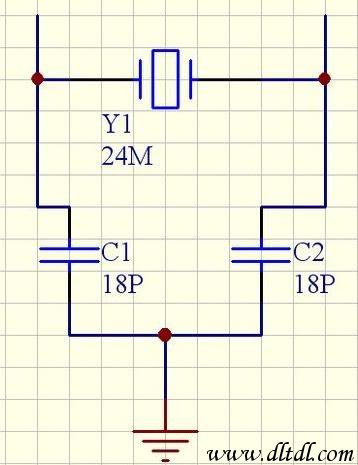
晶振负载电容的计算-其他基础电路图
-
电阻器好坏的判断与检测-其他基础电路图
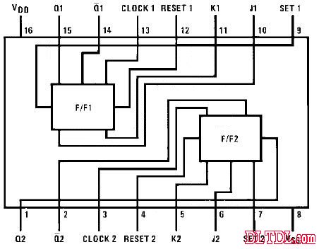
CD4027中文资料-其他基础电路图
-
提高功率因数的方法-其他基础电路图
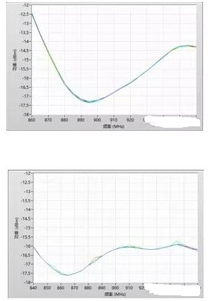
超高频射频识别标签灵敏度的测试方法及解决方案-其他基础电路图
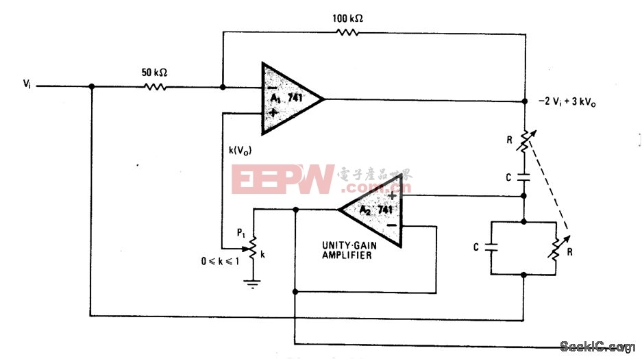
可选择带宽的NOTCH滤波器-其他基础电路图
简易电平转换电路图-其他基础电路图

焊锡技术-教你怎样使焊锡点光亮-其他基础电路图
采用CMOS或非门的防抖动电路-其他基础电路图
LM7824A中文资料-其他基础电路图
具有75欧同辅导线的阻抗-其他基础电路图