您现在的位置是:主页 > 基础 > 其他基础电路图 >
低成本自动应急灯电路,Lowcost/AutomaticEmergencyLight-其他基础电路图
发布时间:2023-03-07 21:42:48所属栏目:其他基础电路图 已帮助人编辑作者:电路图知识网
低成本自动应急灯电路,Low cost/Automatic Emergency Light
Description
--------------------------------------------------------------------------------
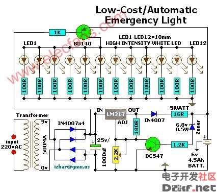
Here is a white-LED-based emergency light that offers the following advantages:
1. It is highly bright due to the use of white LEDs.
2. The light turns on automatically when mains supply fails, and turns off when mains power resumes.
3. It has its own battery charger. When the battery is fully charged, charging stops automatically.
The circuit comprises two sections: charger power supply and LED driver.The charger power supply section is
built around 3-terminal adjustable regulator (IC1) LM317, while the LED driver section is built around transistor BD140(T2). In the charger power supply section, input AC mains is stepped down by transformer to deliver 9V, 500mA to the bridge rectifier, which comprises diodes (IN4007x4). Filter capacitor (25v/1000uf)eliminates ripples. Unregulated DC voltage is fed to input pin 3 of IC1 and provides charging current through diode IN4007(D5) and limiting resistor (16ohm)R16. By adjusting preset 2.2K(VR1), the output voltage can be adjusted to deliver the required charging current. When the battery gets charged to 6.8V, zener diode conducts and charging current from regulator (IC1) finds a path through transistor BC547(T1) to ground and it stops charging of the battery. The LED driver section uses a total of twelve 10mm white LEDs. All the LEDs are connected in parallel with a 100-ohm resistor in series with each. The common-anode junction of all the twelve LEDs is connected to the collector of pnp transistor T2 and the emitter of transistor T2 is directly connected to the positive terminal of 6V battery. The unregulated DC voltage, produced at the cathode junction of Bridge(Diodes), is fed to the base of transistor T2 through a 1k resistor. When mains power is available, the base of transistor T2 remains high and T2 does not conduct. Thus LEDs are off. On the other hand, when mains fails, the base of transistor T2 becomes low and it conducts. This makes all the LEDs (LED1 through LED12) glow. The mains power supply, when available, charges the battery and keeps the LEDs off as transistor T2 remains cut-off. During mains failure, the charging section stops working and the battery supply makes the LEDs glow. Assemble the circuit on a general-purpose PCB and enclose in a cabinet with enough space for battery and switches. Mount the LEDs on the cabinet such that they light up the room. A hole in the cabinet should be drilled to connect 230V AC input for the primary of the transformer. I have tested the circuit with twelve 10mm white LEDs.You can use more LEDs provided the total current consumption does not exceed 1.5A. Driver transistor T2 can deliver up to 1.5A with proper heat-sink arrangement.
Tags:
相关文章
猜你喜欢

可控硅与场效应管及三极管的区别-其他基础电路图
可控硅与场效应管及三极管的区别 1.场效应管的源极s、栅极g、漏极d分别对应...
CD4071 CD4081中文资料_CD4071功能引脚图_CD4081应用电路图-其他基础电路图
CD4071 四2输入端或门OR NSC/TI CD4081 四2输入端与门AND NSC/HIT/TI CD4071真值表:Y=A+B...
采用RS触发器的防抖电路-其他基础电路图
所示为采用RS触发器的防抖动电路。由图可 知,在开关的触点部位加了RC积分电...
由T触发器组成的非同步即使输球电路及其信号波形-其他基础电路图
所示是利用T触发器组成的计数器电路及其信号波形,它是一种非同步式计数器...

其他基础电路图相关资讯
-
电阻器好坏的判断与检测-其他基础电路图
可选择带宽的NOTCH滤波器-其他基础电路图
供电耦合器一晶闸管的接口电路a-其他基础电路图
采用CMOS或非门的防抖动电路-其他基础电路图
超高频射频识别标签灵敏度的测试方法及解决方案-其他基础电路图
晶振负载电容的计算-其他基础电路图
具有75欧同辅导线的阻抗-其他基础电路图
简易电平转换电路图-其他基础电路图
经典实用的单片机模块电路设计_单片机电路图-其他基础电路图

焊锡技术-教你怎样使焊锡点光亮-其他基础电路图
多路脉冲编码器-其他基础电路图
LM7824A中文资料-其他基础电路图
-
提高功率因数的方法-其他基础电路图
CD4027中文资料-其他基础电路图
稳压用运算放大器基本电-其他基础电路图