您现在的位置是:主页 > 基础 > 其他基础电路图 >
SurveillanceTransmitterDetector-其他基础电路图
发布时间:2022-09-14 10:04:57所属栏目:其他基础电路图 已帮助人编辑作者:电路图知识网
Surveillance Transmitter Detector

Notes:
My site contains a few low power transmitters of style="WIDTH: 523px; HEIGHT: 402px" height=99 src="/data/attachment/portal/201007/ET31001201007221057532.jpg" width=122 onload=javascript:resizepic(this) border=0>
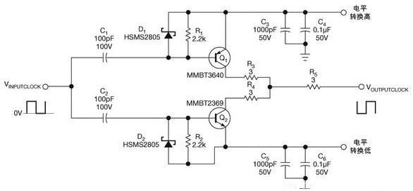
Circuit operation is simple. The inductor is a moulded RF coil, value of 0.389uH and is available from Maplin Electronics, order code UF68Y. (See my links page for component suppliers.) The coil has a very high Q factor of about 170 and is untuned or broadband. With a test oscillator this circuit responded to frequencies from 70 MHz to 150 MHz, most of the FM bugs are designed to work in the commercial receiver range of 87 - 108 MHz. The RF signal picked up the coil, and incidentally this unit will respond to AM or FM modulation or just a plain carrier wave, is rectified by the OA91 diode. This small DC voltage is enough to upset the bias of the FET, and give an indication on the meter. The FET may by MPF102 or 2N3819, the meter shown in the picture is again from Maplin Electronics, order code LB80B and has a 250 uA full scale deflection. Meters with an FSD of 50 or 100 uA may be used for higher sensitivity.
Tags:
相关文章
猜你喜欢

可控硅与场效应管及三极管的区别-其他基础电路图
可控硅与场效应管及三极管的区别 1.场效应管的源极s、栅极g、漏极d分别对应...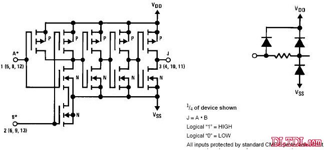
CD4071 CD4081中文资料_CD4071功能引脚图_CD4081应用电路图-其他基础电路图
CD4071 四2输入端或门OR NSC/TI CD4081 四2输入端与门AND NSC/HIT/TI CD4071真值表:Y=A+B...
采用RS触发器的防抖电路-其他基础电路图
所示为采用RS触发器的防抖动电路。由图可 知,在开关的触点部位加了RC积分电...
由T触发器组成的非同步即使输球电路及其信号波形-其他基础电路图
所示是利用T触发器组成的计数器电路及其信号波形,它是一种非同步式计数器...

其他基础电路图相关资讯
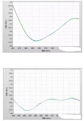
超高频射频识别标签灵敏度的测试方法及解决方案-其他基础电路图
采用CMOS或非门的防抖动电路-其他基础电路图
多路脉冲编码器-其他基础电路图
具有75欧同辅导线的阻抗-其他基础电路图
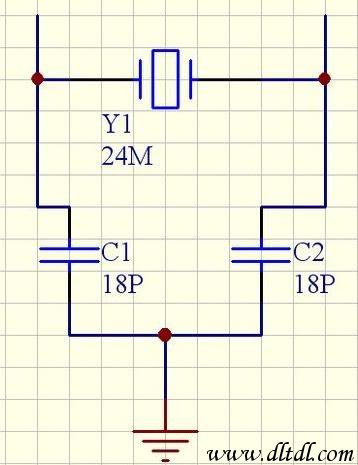
晶振负载电容的计算-其他基础电路图
稳压用运算放大器基本电-其他基础电路图
-
电阻器好坏的判断与检测-其他基础电路图
简易电平转换电路图-其他基础电路图
经典实用的单片机模块电路设计_单片机电路图-其他基础电路图
LM7824A中文资料-其他基础电路图
可选择带宽的NOTCH滤波器-其他基础电路图
-
提高功率因数的方法-其他基础电路图

焊锡技术-教你怎样使焊锡点光亮-其他基础电路图
供电耦合器一晶闸管的接口电路a-其他基础电路图
CD4027中文资料-其他基础电路图