您现在的位置是:主页 > 基础 > 其他基础电路图 >
简单的LED电源项目电路ApowersourceforsimpleLEDprojects-其他基础电路图
发布时间:2022-11-19 18:22:26所属栏目:其他基础电路图 已帮助人编辑作者:电路图知识网
简单的LED电源项目电路 A power source for simple LED projects
LED's are great display tools. Their prices have decreased to a point where they are replacing more conventional light sources. In border=0>
The 10 LED's were lit using the following circuit...
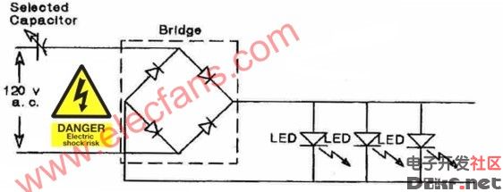
figure 2
The capacitor value may be computed via the following empirical formula. This formula is valid for the circuit shown in Fig.2:
 (1)
(1)
Where "C" is in uFd and "I" is in miliamperes. A design current of 10 mA per LED was selected. Thus for ten LED's, 100mA is the total current. Inserting this current value into the formula, yields a capacitor value of 3.1uFd.
To achieve this value, two capacitors connected in parallel were used. Recall that the total capacitance of capacitors connected in parallel is simply the arithmetic sum of the individual capacitors:

Thus:


figure 3
If it becomes necessary to use capacitors connected in series to achieve a desired total capacitance, the formula for this computation is:

For two capacitors in series, it may be easier to calculate the total series capacitance via:

To achieve a desired total capacitance, it may be necessary to use a series-parallel connection of three capacitors. Empirical formula (1) was derived by measuring currents and voltages for various quantities of LED's (up to 30) connected into the circuit shown in Fig 2. The capacitors must be low loss, non-polarized units with voltage ratings equal to or greater than 200 volts.
Transformer voltage dropping circuit
If instead of using capacitors, it is desired to power LED's with a transformer, the low voltage, rectified sine wave ideally should be applied to each LED via a dropping resistor. This enables the forward current to be adjusted to a value that does not overdrive the LED. In lieu of using dropping resistors, if the rectified voltage is carefully selected via a judicious choice of transformer, the output of a rectifier may be applied directly to align=left>
figure 4
The Tamura transformer has a 4 volts c.t secondary. This value just supplies sufficient voltage to generate 14mA for align=left>Comparing the two approaches, the capacitor voltage dropping circuit is smaller, lighter in weight and varying the capacitor value enables the user to obtain a desired current value for each LED. The transformer approach, yields a circuit where the transformer provides isolation between the LED's and the line voltage. Both circuits are nominally low in parts cost.
Parts
The components used in gathering data where purchased from Mouser Electronics:
- 2.2 uFd = PHE840MZ7220MF14R (2.52)
- 1.0 uFd = PHE840MY7100MD16R (0.93) (275 Volts)
- Tamura transformer #SB2812-1204 (3.53)
- 1N4004 diodes (0.08 each)
The bridge rectifier and LED's were purchased from All Electronics:
- LED-1 (T1-3/4 Red LED) (0.10 each)
- FWB-15, 1-1/2 amp, 400 PIV Bridge Rectifier (0.50 each)
- Perf Board
Acknowledgments: My thanks to Mr. Oscar Ramsey for his testing, data gathering and construction efforts.
Tags:
相关文章
猜你喜欢

可控硅与场效应管及三极管的区别-其他基础电路图
可控硅与场效应管及三极管的区别 1.场效应管的源极s、栅极g、漏极d分别对应...
CD4071 CD4081中文资料_CD4071功能引脚图_CD4081应用电路图-其他基础电路图
CD4071 四2输入端或门OR NSC/TI CD4081 四2输入端与门AND NSC/HIT/TI CD4071真值表:Y=A+B...
采用RS触发器的防抖电路-其他基础电路图
所示为采用RS触发器的防抖动电路。由图可 知,在开关的触点部位加了RC积分电...
由T触发器组成的非同步即使输球电路及其信号波形-其他基础电路图
所示是利用T触发器组成的计数器电路及其信号波形,它是一种非同步式计数器...

其他基础电路图相关资讯
晶振负载电容的计算-其他基础电路图
多路脉冲编码器-其他基础电路图
稳压用运算放大器基本电-其他基础电路图
采用CMOS或非门的防抖动电路-其他基础电路图
-
提高功率因数的方法-其他基础电路图
-
电阻器好坏的判断与检测-其他基础电路图
供电耦合器一晶闸管的接口电路a-其他基础电路图
具有75欧同辅导线的阻抗-其他基础电路图
超高频射频识别标签灵敏度的测试方法及解决方案-其他基础电路图

焊锡技术-教你怎样使焊锡点光亮-其他基础电路图
简易电平转换电路图-其他基础电路图
LM7824A中文资料-其他基础电路图
经典实用的单片机模块电路设计_单片机电路图-其他基础电路图
可选择带宽的NOTCH滤波器-其他基础电路图
CD4027中文资料-其他基础电路图