您现在的位置是:主页 > 音频 > 其他音频电路图 >
带低音增强的立体声前置放大器电路 (Stereo Pream-其他音频电路图
发布时间:2023-01-31 10:03:56所属栏目:其他音频电路图 已帮助人编辑作者:电路图知识网
带低音增强的立体声前置放大器电路 (Stereo Preamplifier with Bass-boost)
gh Quality, simple design 20 to 30V supply
Parts:
P1_________________10K Log.PotenTIometer (Dual-gang for stereo)
P2________________100K Log.PotenTIometer (Dual-gang for stereo) (See Notes)
R1,R2_____________100K 1/4W Resistors
R3,R6______________15K 1/4W Resistors
R4_________________10K 1/4W Resistor
R5_________________22K 1/4W Resistor
R7__________________1K 1/4W Resistor
R8________________560R 1/4W Resistor
C1,C2,C5____________2΅2 63V ElectrolyTIc Capacitors
C3________________470΅F 35V ElectrolyTIc Capacitor
C4__________________1΅F 63V Polyester Capacitor
C6_________________47nF 63V Polyester Capacitor
C7_________________22΅F 25V Electrolytic Capacitor
IC1_______________TL072 Dual BIFET Op-Amp
SW1________________DPST Switch (Optional, see Notes)
Comments:
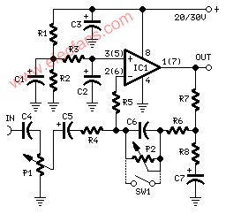
This preamplifier was designed to cope with CD players, tuners, tape recorders etc., providing a gain of 4, in order to drive less sensitive power amplifiers. As modern Hi-Fi home equipment is frequently fitted with small loudspeaker cabinets, the bass frequency range is rather sacrificed. This circuit features also a bass-boost, in order to overcome this problem. You can use a variable resistor to set the bass-boost from 0 to a maximum of +16dB @ 30Hz. If a fixed, maximum boost value is needed, the variable resistor can be omitted and substituted by a switch.
Notes:
Schematic shows left channel only, but R1, R2, R3 and C1, C2, C3 are common to both channels.
For stereo operation P1, P2 (or SW1), R4, R5, R6, R7, R8 and C4, C5, C6, C7 must be doubled.
Numbers in parentheses show IC1 right channel pin connections.
A log type for P2 ensures a more linear regulation of bass-boost.
Needing a simple boost-in boost-out operation, P2 must be omitted and SW1 added as shown in the diagram.
For stereo operation SW1 must be a DPST type.
Please note that, using SW1, the boost is on when the switch is open, and off when the switch is closed.
Technical data (30V supply):
Gain @ 1KHz: 4
Max. input voltage @ 50Hz: 500mV RMS (280mV RMS @ 20V supply)
Max. input voltage @ 100Hz: 700mV RMS (460mV RMS @ 20V supply)
Max. output voltage: >8V RMS (>5V RMS @ 20V supply)
Max. bass-boost referred to 1KHz: 400Hz = +2dB; 200Hz = +5dB; 100Hz = +10dB; 50Hz = +14dB; 30Hz = +16dB
Total harmonic distortion @ 100Hz and 1V RMS output: 0.02%
Total harmonic distortion @ 1KHz and 1V RMS output: 0.006%
Total harmonic distortion @10KHz and 1V RMS output: 0.007%
Total harmonic distortion @ 100Hz and 5V RMS output: 0.02%
Total harmonic distortion @ 1KHz and 5V RMS output: 0.0013%
Total harmonic distortion @10KHz and 5V RMS output: 0.005%
Current drawing: 2mA
Tags:
相关文章

其他音频电路图相关资讯

功放机放音时左右两声道均失真-其他音频电路图
LA4461Namp;nbsp;音响IC电路图-其他音频电路图
用PVC管制成高品质音箱-其他音频电路图
电子蜂鸣器与集成电路NE555定时器-其他音频电路图
-
音箱的寿命与保养-其他音频电路图
TDA1515B功放电路图纸原理图-其他音频电路图
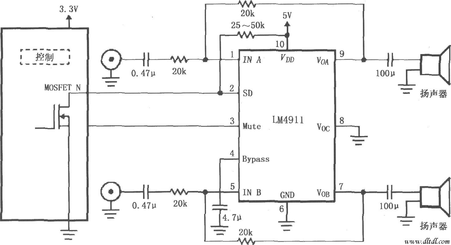
LM4911的不同电源导通时间电路-其他音频电路图
8管OTL耳放的电路图-其他音频电路图

先锋VSX-D906X/D906S/07TX/09TX功放后级电路图-其他音频电路图
柔性剪峰电路-其他音频电路图

电话铃声发生器电路图-其他音频电路图
HFC—L5 6s随机录放语音加音乐成品板-其他音频电路图
LA4497nbsp;音响IC电路图-其他音频电路图
-
PANASONIC CQ-FX35-55LEN汽车音响电路图-其他音频电路图
粉红噪声发生器-其他音频电路图