您现在的位置是:主页 > 信号产生 > 其他信号产生器电路图 >
BH1417调频立体声发射机(英文)-----FM Stereo Transmitter circuit diagram Using B-其他信号产生器电路图
发布时间:2022-12-06 01:04:12所属栏目:其他信号产生器电路图 已帮助人编辑作者:电路图知识网
FM Stereo Transmitter circuit diagram Using BH1417This circuit is a circuit diagram is included in the RF circuit. FM Transmitter circuit diagram using the IC BH1417. Where the integrated circuit design from RHOM which includes many features in one small package. He came with pre-emphasis, limiter so that music can be transmitted in the same audio level, stereo encoder for stereo transmission, low pass filter that blocks audio signals above 15KHz to prevent RF interference, PLL circuit that provides a solid frequency transmission (no more frequency drift), FM oscillator and RF output buffer. The following is a schematic drawing:There are 14 possible transmission frequencies with 200KHz adding that the user can choose a 4-DIP switch. Band lower frequency ranging from 88.7 to 89.9 MHz, and the frequency band from 107.7 to 108.9 MHz. BH1417 can be given with 4-6 voltage and consumes only around 30mA, provides RF power output of 20mW. BH1417 provides 40db channel separation is quite good, although older BA1404 FM Transmitter chip provides 45dB channel separation a little better.Source: electronics-diy.com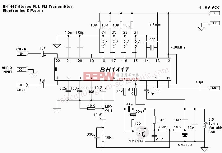
Tags:
相关文章
- 八8进制计数器电路图多种频率信号 电路图 -其他信号产生器电路图
- CD4093的正弦波转方波电路图多种频率信号 电路图 -其他信号产生器电路图
- 差动放大器的电流控制方式电路图信号发生 电路图 -其他信号产生器电路图
- 4kHz谐波发生器电路图中频信号产生 电路图 -其他信号产生器电路图
- 简易方波振荡器电路图振荡电路 电路图 -其他信号产生器电路图
- 一个多用途信号发生器电路图信号发生 电路图 -其他信号产生器电路图
- V/F转换器-其他信号产生器电路图
- 256进制计数器电路图多种频率信号 电路图 -其他信号产生器电路图
- 1.5V操作的455kHz中频放大器电路图-其他信号产生器电路图
- 振荡器电路信号产生 电路图 -其他信号产生器电路图
猜你喜欢
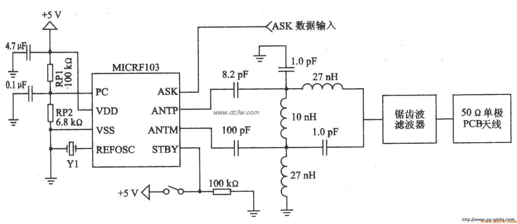
l GHz~800MHz ASK发射器-其他信号产生器电路图
l GHz~800MHz ASK发射器MICRFl03特点及应用电路 MICRFl03是使用Micrels QwikRadioTM技术的...
新型附加晶体管减少单稳态多谐振荡器电路信号产生 电路图 -其他信号产生器电路图
在脉冲输出期间,R6使Q2截止,电路作用和一般的单稳态多谐振荡器一样。当脉...
144到2304 MHz的超高频宽带放大器高频信号产生 电路图 -其他信号产生器电路图
基于一个MAR6前置放大器,这个电路产生低噪声的图像,用于144MHz到2304MHz的业余...
采用MAR-1单片微波集成电路的接收器扫描仪前置放大器信号产生 电路图 -其他信号产生器电路图
带有固定50Ω输入和输出抗阻(射频系统所需的),这个低成本的微型电路MAR...

其他信号产生器电路图相关资讯
CCD模拟输出信号处理电路图信号发生 电路图 -其他信号产生器电路图

反相积分运算电路图信号发生 电路图 -其他信号产生器电路图

京华JW-A21微型收音机电-其他信号产生器电路图
锯齿波触发脉冲发生器信号产生 电路图 -其他信号产生器电路图
阶梯波发生器信号产生 电路图 -其他信号产生器电路图
频率和振幅稳定的正弦波输出电路图振荡电路 电路图 -其他信号产生器电路图
可以调节占控比的脉冲振荡器信号产生 电路图 -其他信号产生器电路图
克拉泼信号发生器电路图宽带信号产生 电路图 -其他信号产生器电路图
单脉冲发生器电路图-其他信号产生器电路图
RF功率控制电路的电压级设定电路图宽带信号产生 电路图 -其他信号产生器电路图
555组成的占空比可调的多谐振荡器电路图多谐振荡产生 电路图 -其他信号产生器电路图
变节奏的信号产生电路图多谐振荡产生 电路图 -其他信号产生器电路图
计数左脉宽倍增器电路图脉冲信号产生器 电路图 -其他信号产生器电路图
音乐电视的信号发生器电路信号产生 电路图 -其他信号产生器电路图
电路之RC相移式振荡器电路图振荡电路 电路图 -其他信号产生器电路图