您现在的位置是:主页 > 通信 > 通信综合电路图 >
使用非门电路制作的调频话筒(英文),FM Transmitter Using Logic Gates-通信综合电路图
发布时间:2022-12-12 20:38:37所属栏目:通信综合电路图 已帮助人编辑作者:电路图知识网
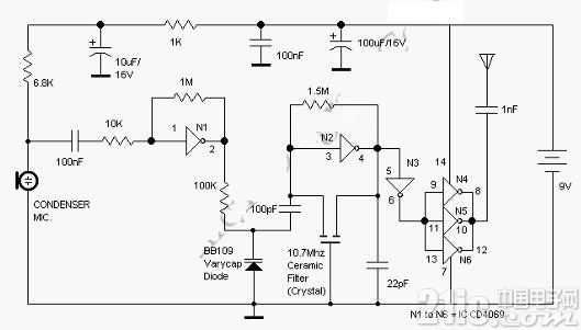
This is a FM Transmitter circuit. This circuit uses logic gates. This transmitter circuit has a RF oscillator. This oscillator uses 10.7Mhz ceramic filter and inverter N2 to drive the parallel combination of N4 to N6 through N3. Here is the circuit:
The output impedance will be low because these inverters are in parallel, so an aerial of 1/4h wavelength can be driven directly. There would be a lot of harmonics in the output of N4-N6 because the output of N4 to N6 is square wave. The 9th harmonics of 10.7Mhz (96.3Mhz) will hence be at the center of the FM band. As an audio amplifier, this circuit uses N1. It will amplify audio signals from the microphone and fed it to varycap diode. The capacitance of the varycap is varied by the signal that will vary the oscillator frequency that produce Frequency Modulation.
Tags:
相关文章


通信综合电路图相关资讯

用于智能标签的运动感知薄型低功耗蓝牙信标解决方案-通信综合电路图

基于软件无线电的通信系统试验平台的设计实现,软硬件原理、架构-通信综合电路图
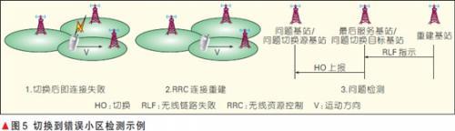
LTE/LTE-A系统自组织网络技术和标准化进展-通信综合电路图
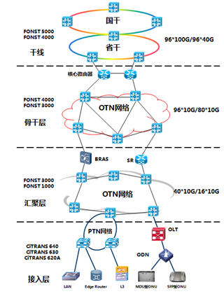
三网融合传输网络解决方案-通信综合电路图

12x10G带宽的可插拔光纤收发器模块,链路距离300米-通信综合电路图
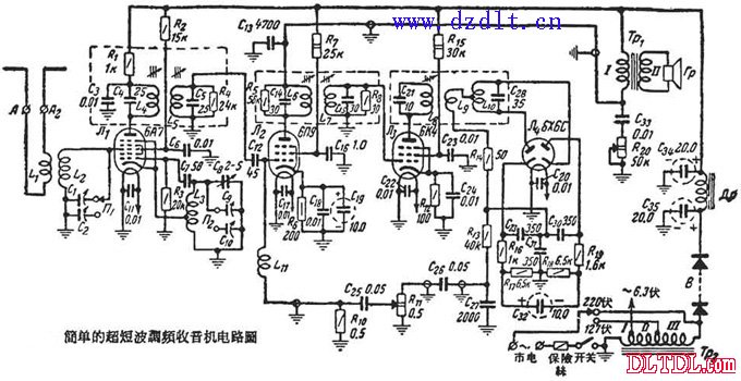
超短波调频收音机电路图-通信综合电路图

基于Android平台的即时通信系统客户端设计-通信综合电路图
LM386应用于收音机中的电路-通信综合电路图
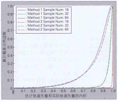
压缩感知技术在未来移动通信系统中的应用-通信综合电路图

大时钟,小基站,一颗芯片满足微基站不同外设的时钟需求-通信综合电路图
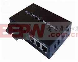
RS-232/485/422单模单纤解决方案-通信综合电路图
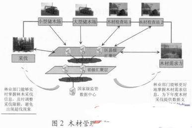
物联网技术在木材管理领域的应用-通信综合电路图
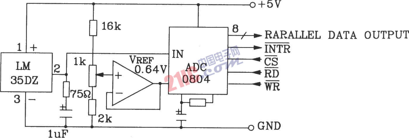
LM35DZ构成并行三态输出标准微机电路-通信综合电路图
收音机动态调试-通信综合电路图
电源滤波去耦网络的应用-通信综合电路图