您现在的位置是:主页 > 控制 > 其他控制电路图 >
汽车电池充电器电路(CarBatteryCharger)-其他控制电路图
发布时间:2022-11-26 13:40:39所属栏目:其他控制电路图 已帮助人编辑作者:电路图知识网
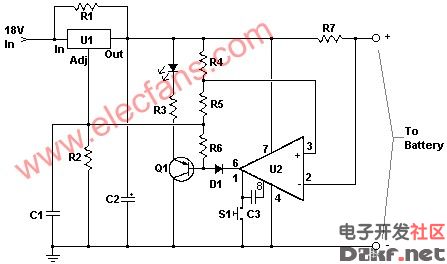
汽车电池充电器电路 (Car Battery Charger)
This charger will quickly and easily charge most any lead acid battery. The charger delivers full current until the current drawn by the battery falls to 150 mA. At this time, a lower voltage is applied to finish off and keep from over charging. When the battery is fully charged, the circuit switches off and lights a LED, telling you that the cycle has finished.
Schematic
Parts
Part
Total Qty.
Description
Substitutions
R1
1
500 Ohm 1/4 W Resistor
R2
1
3K 1/4 W Resistor
R3
1
1K 1/4 W Resistor
R4
1
15 Ohm 1/4 W Resistor
R5
1
230 Ohm 1/4 W Resistor
R6
1
15K 1/4 W Resistor
R7
1
0.2 Ohm 10 W Resistor
C1
1
0.1uF 25V Ceramic Capacitor
C2
1
1uF 25V Electrolytic Capacitor
C3
1
1000pF 25V Ceramic Capacitor
D1
1
1N457 Diode
Q1
1
2N2905 PNP Transistor
U1
1
LM350 Regulator
U2
1
LM301A Op Amp
S1
1
Normally Open Push Button Switch
MISC
1
Wire, Board, Heatsink For U1, Case, Binding Posts or Alligator Clips For Output
Notes
1. The circuit was meant to be powered by a power supply, which is why there is no transformer, rectifier, or filter capacitors border=0>
Part
Total Qty.
Description
Substitutions
C1
1
6800uF 25V Electrolytic Capcitor
T1
1
3A 15V Transformer
BR1
1
5A 50V Bridge Rectifier
10A 50V Bridge Rectifier
S1
1
5A SPST Switch
F1
1
4A 250V Fuse
5. The first time you use the circuit, you should check up on it every once and a while to make sure that it is working properly and the battery is not being over charged.
Tags:
下一篇:电话交换机原理图-其他控制电路图
相关文章

其他控制电路图相关资讯
采用UAA1016B集成电路的恒温控制电路-其他控制电路图
隧道二极管双稳态电路-控制电路-其他控制电路图

峰值检知器电路(Peakdetector)-其他控制电路图
卫生间门控开关电路(四)-控制电路-其他控制电路图
1.5V低电源音频电平检测电路-其他控制电路图
液晶显示电子温度表电路-控制电路-其他控制电路图

能驱动继电器的射极耦合单稳态电路-控制电路-其他控制电路图

5通道低功耗可编程传感器信号处理器AD7714和微处理器构成的隔离-其他控制电路图
简易变光拉线开关电路-控制电路-其他控制电路图
棉花湿度检测电路-其他控制电路图
简单的LED闪光灯电路图-其他控制电路图

采用晶体管的湿度控制电路-其他控制电路图
生物芯片扫描仪弱信号检测方法-其他控制电路图
555简易恒温控制器电路-控制电路-其他控制电路图
采用功率开关集成电路的恒温控制电路-其他控制电路图