您现在的位置是:主页 > 控制 > 其他控制电路图 >
Synchronizedmulti-sparkmodule(SMSM)forElectronicIgnitionDevices(EID)-其他控制电路图
发布时间:2023-04-23 07:14:15所属栏目:其他控制电路图 已帮助人编辑作者:电路图知识网
Synchronized multi-spark module (SMSM) for Electronic Ignition Devices (EID)
Multi-spark ignition is very useful especially in the case of startings at low temperature and at low rpm range. Basic idea, is to apply to spark plugs instead of border=0>
where :
n = revolution speed of engine crankshaft (rpm)
M = strokes number (2 or 4)
N = number of sparks per second (sparks frequency, in Hz)
B = number of ignition coils
C = cylinder number
For usual four stroke engines, with 4 cylinders and a single ignition coil, the formula becomes :

From where :

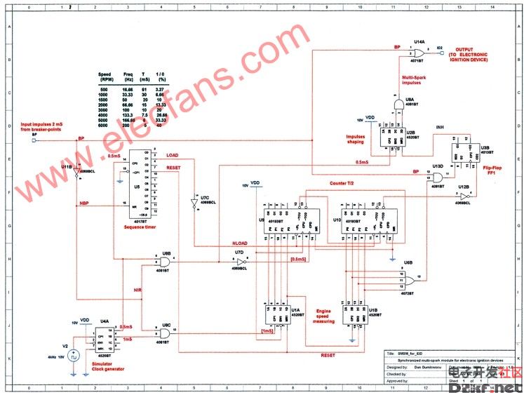
In fig.1 is shown an EID equipped with synchronized multi-spark module.
Shaping block has the role to provide fixed length impulses (2 mS) at each breaker-points opening. In this way are eliminated the false impulses which appear due contacts vibrations.
As shown in drawing, shaped impulse triggers directly the EID and act as START impulse for multi-spark module. If rpm of engine is under speed limit, the module will generate a series of supplementary impulses that, through an OR gate, will generate supplementary sparks by EID. When speed limit is reached (for example, 2000 rpm), supplementary impulses stops at module output, thus no supplementary sparks will be generated.
Functional description
The module uses for control the shaped impulses from breaker points. The time between two consecutively impulses depends border=0>
From whole T interval, height=563 src="/data/attachment/portal/201007/ET32525201007222331486.gif" width=628 border=0>
In multi-spark module, during 2 mS interval, a sequence timer (a counter with decoded outputs) accomplishes the initialization of circuits (full operations will be detailed later). When impulse BP disappears, the gate P2 is opened and the counter N1 receives impulses with 1 mS period, from clock generator. This 8 bits counter measures, in fact, the duration between two breaker-points impulses. It can count maximum 255 impulses, each having 1 mS (see the table, this correspond to 120 rpm, far below the free running speed !). At next BP impulse, P2 close and the counting stop. The number stored inside N1 is in fact the time length between two BP impulses.
The sequence timer copy the number stored in N1 to N2, after this resets counter N1. When BP becomes low level, N1 restarts the counting. In the same time, the up/down counter N2, starts counting the impulses having 0.5 mS period, which comes via gate P1. It counts down, but with double speed. In this way the counter N2 reach to 0 after T/2 time. The counter N4 and gate P5 makes the impulses for supplementary sparks (2 mS length).
This counter works only if INH signal is at low level. The fip-flop FF1 marks the interval T/2 in which will be generated supplementary sparks. It is reseted when N2 reach 0. The gates P3 and P4 unlock the flio-flop and start supplementary sparks. Also, these gates switch-off the multi-spark function when engine speed limit is reached (in this case, ~ 2000 rpm). How works this ? In the upper table we can see at about 2000 rpm, the time length between two BP impulses is 15 mS.
This means as after a counting cycle, the first 4 bits of counter N1 will be 111 and next 4, 0000. In this case, P3 gate output will be at low level, and the same value for P4 output. The flip-flop FF1 will be not set, and as result, no supplementary sparks. If the speed engine decrease (time length T increase), the last 4 bits of N1 will have at least one 1 and the flip-flop will be set. This allow to appear supplementary sparks until flip-flop will be reseted by borrow impulse of N2.
The module can be maked like a plug-in adapter for an EID.
Tags:
相关文章

其他控制电路图相关资讯
液晶显示电子温度表电路-控制电路-其他控制电路图

峰值检知器电路(Peakdetector)-其他控制电路图
555简易恒温控制器电路-控制电路-其他控制电路图

采用晶体管的湿度控制电路-其他控制电路图

5通道低功耗可编程传感器信号处理器AD7714和微处理器构成的隔离-其他控制电路图
采用UAA1016B集成电路的恒温控制电路-其他控制电路图
棉花湿度检测电路-其他控制电路图
生物芯片扫描仪弱信号检测方法-其他控制电路图
1.5V低电源音频电平检测电路-其他控制电路图
简易变光拉线开关电路-控制电路-其他控制电路图
采用功率开关集成电路的恒温控制电路-其他控制电路图
卫生间门控开关电路(四)-控制电路-其他控制电路图
简单的LED闪光灯电路图-其他控制电路图

能驱动继电器的射极耦合单稳态电路-控制电路-其他控制电路图
隧道二极管双稳态电路-控制电路-其他控制电路图