您现在的位置是:主页 > 控制 > 其他控制电路图 >
汽车电子点火电路(Electroniccarignition)-其他控制电路图
发布时间:2022-09-10 22:23:01所属栏目:其他控制电路图 已帮助人编辑作者:电路图知识网
汽车电子点火电路 (Electronic car ignition)
click image for higher resolution
ATTENTION: Don't construct this project until this label is removed. There are some corrections that must be done in order to be full working. Sorry for the inconvenience.
Description:
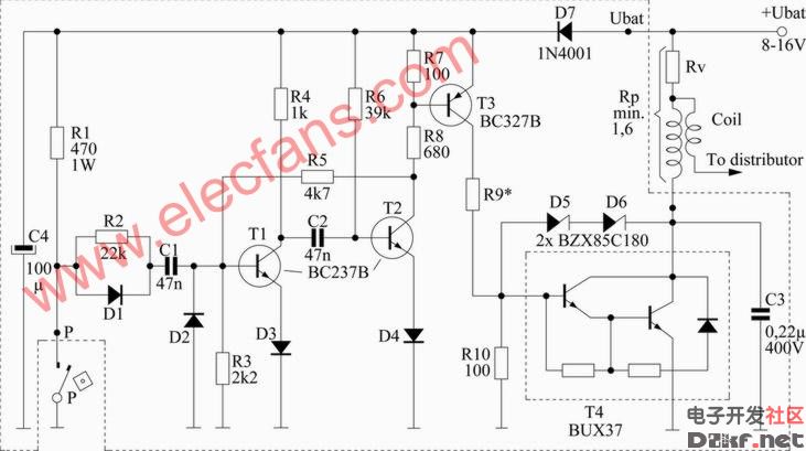
This scheme is for 4 cylinder motor. This will make your car spent less fuel, be a little bit faster and you wont have to frequently open your distributor cap to change the contact buttons thus wasting less money.
T1/T2 create one monostable multivibrator in which C2 and R5 determine the length of impulse which is 1,5 msec. Next in line are T3 and then T4 which is Darlington transistor specially developed for electronic ignition which is used as a switch to turn on/off primary coil. Impulses from switch P turn on monostable multivibrator T1/T2. You need to un-connect capacitor that is in distributor cap because it is not needed anymore. While switch P is closed T1 is in off state but T2 is in on state, also T3 and T4 which enables current to flow trough primary coil. When switch P is opened, T1 gets in on state for a moment causing C2 to charge over R6 which makes T2 go to off state because of voltage drop on R6. When T2 is off also T3 and T4 are off and current that was flowing trough primary coil is stopped. Because T2 is in off state, voltage on R8 is increased which is passed trough R5 on T1 base which is still in on state and C2 is still charging. After 1,5 msec. C2 value reaches the level where T2 goes to on state again and T1 goes to off state. Now T2, T3 and T4 are in on state, again, and current flows trough primary coil again. R2 and D1 are used to neutralize the effect of impulses caused from «jumping» of switch P which could turn on monostable multivibrator when it shouldn't.
Zener diodes Z5 and Z6 are together with R10 limit overcharged voltage impulses that are caused by self induction of primary coil which could damage T4. They should be connected as close as possible to T4.
D7 protects device from wrong polarity.
Coil should have ratio of 1:80 or 1:100 with external resistor Rv which is used for better cooling. Total resisting value (Rp) of primary coil and Rv resistor shouldn't be under 1,6 ohm's so current trough T4 wouldnt be bigger than 10A.
Depending on Rp, R9 have different values:
120Ω/2W for Rp tot 2,2Ω
100Ω/2W for 1,8Ω Rp tot 2,2Ω
82Ω/3W for 1,5Ω Rp tot 1,8Ω
T4 has to be heatsinked!!!
All resistors are 1/2W +/-5%
Parts:
D1-D4 = 1N4148
D5-D6 = BZX85C 180 (replicable with all equivalent types with power of 1,3W)
D7 = 1N4001
R1 = 470 - 1W
R2 = 22k
R3 = 2,2k
R4 = 1k
R5 = 4,7k
R6 = 39k
R7 R10 = 100
R8 = 680
C1 C2 = 47nF (ceramic)
C3 = 0,22uF 400V (ceramic)
C4 = 100uF (electrolytic)
T1 T2 = BC327 (BC327-25, BC327-40)
T3 = BC237B (BC547B, BC547C)
T4 = BUX37 (BU323, BU920, BU921, BU922, BUV37B (u TOP3), BUW29, BUW81, MJ10012, MJ10013, MJ10014, TIP662, TIP665, 2SD683)
Tags:
下一篇:固态自动调节器-其他控制电路图
相关文章

其他控制电路图相关资讯
555简易恒温控制器电路-控制电路-其他控制电路图
采用UAA1016B集成电路的恒温控制电路-其他控制电路图
生物芯片扫描仪弱信号检测方法-其他控制电路图
简单的LED闪光灯电路图-其他控制电路图

能驱动继电器的射极耦合单稳态电路-控制电路-其他控制电路图

采用晶体管的湿度控制电路-其他控制电路图

5通道低功耗可编程传感器信号处理器AD7714和微处理器构成的隔离-其他控制电路图
采用功率开关集成电路的恒温控制电路-其他控制电路图
棉花湿度检测电路-其他控制电路图
液晶显示电子温度表电路-控制电路-其他控制电路图
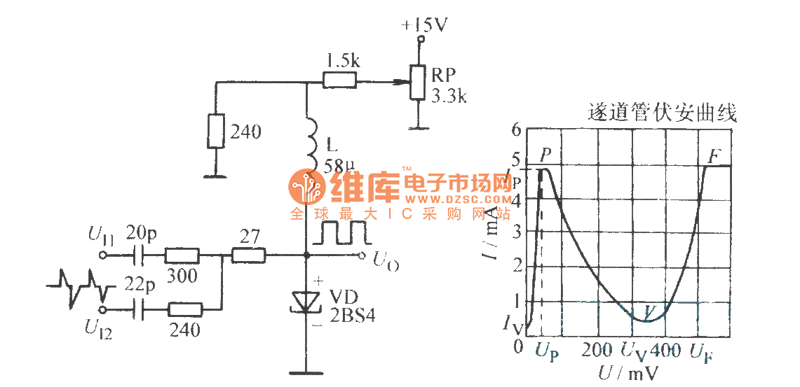
隧道二极管双稳态电路-控制电路-其他控制电路图
1.5V低电源音频电平检测电路-其他控制电路图

峰值检知器电路(Peakdetector)-其他控制电路图
卫生间门控开关电路(四)-控制电路-其他控制电路图
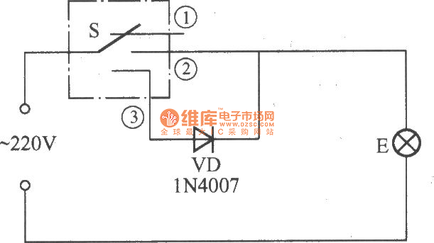
简易变光拉线开关电路-控制电路-其他控制电路图