您现在的位置是:主页 > 控制 > 其他控制电路图 >
模块化的防盗系统-控制电路-其他控制电路图
发布时间:2023-04-05 15:12:06所属栏目:其他控制电路图 已帮助人编辑作者:电路图知识网
4001BC547
This circuit features automatic Exit and Entry delays and a timed Bell Cut-off. It has provision for both normally-closed and normally-open contacts, and a 24-hour Personal Attack/Tamper zone. It is connected permanently to the 12-volt supply and its operation is "enabLED" by opening SW1. By using the expansion modules, you can add as many zones as you require; some or all of which may be the inertia (shock) sensor type. All the green LEDs should be lighting before you open SW1. You then have up to about a minute to leave the building. As you do so, the Buzzer will sound. It should stop sounding when you shut the door behind you. This indicates that the Exit/Entry loop has been successfully restored within the time allowed. When you re-enter the building you have up to about a minute to move SW1 to the off position. If SW1 is not switched off in time, the relay will energise and sound the main bell. It will ring for up to about 40 minutes. But it can be turned off at any time by SW1. The "Instant" zone has no Entry Delay. If you don"t want to use N/O switches, leave out R8, C8 and Q2; and fit a link between Led 3 and C7. The 24 Hour PA/Tamper protection is provided by the SCR/Thyristor. If any of the switches in the N/C loop is opened, R11 will trigger the SCR and the bell will ring. In this case the bell has no time limit. Once the loop is closed again, the SCR may be reset by pressing SW2 and temporarily interrupting the current flow. The basic circuit will be satisfactory in many situations. However, it"s much easier to find a fault when the alarm is divided into zones and the control panel can remember which zone has caused the activation. The expansion modules are designed to do this. Although they will work with the existing instant zone, they are intended to replace it. When a zone is activated, its red LED will light and remain lit until the reset button is pressed. All the modules can share a single reset button. The Stripboard layout of the prototype is available.
Tags:
相关文章

其他控制电路图相关资讯
简单的LED闪光灯电路图-其他控制电路图
卫生间门控开关电路(四)-控制电路-其他控制电路图

能驱动继电器的射极耦合单稳态电路-控制电路-其他控制电路图

峰值检知器电路(Peakdetector)-其他控制电路图
555简易恒温控制器电路-控制电路-其他控制电路图
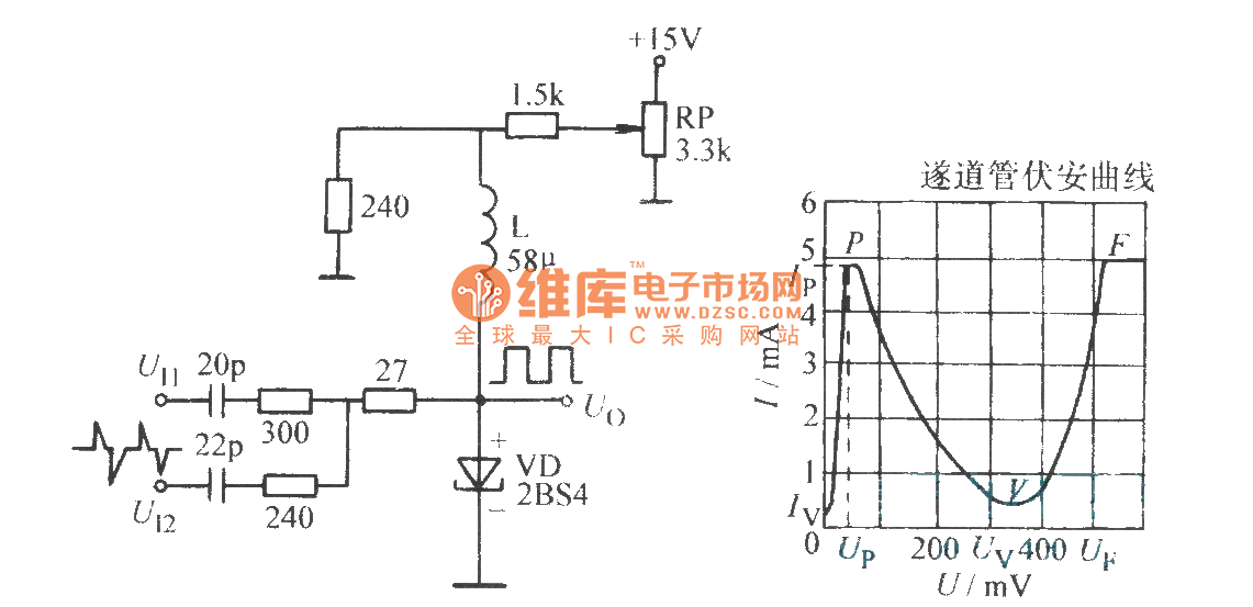
隧道二极管双稳态电路-控制电路-其他控制电路图

采用晶体管的湿度控制电路-其他控制电路图
生物芯片扫描仪弱信号检测方法-其他控制电路图
1.5V低电源音频电平检测电路-其他控制电路图
采用功率开关集成电路的恒温控制电路-其他控制电路图
液晶显示电子温度表电路-控制电路-其他控制电路图
棉花湿度检测电路-其他控制电路图
采用UAA1016B集成电路的恒温控制电路-其他控制电路图

5通道低功耗可编程传感器信号处理器AD7714和微处理器构成的隔离-其他控制电路图
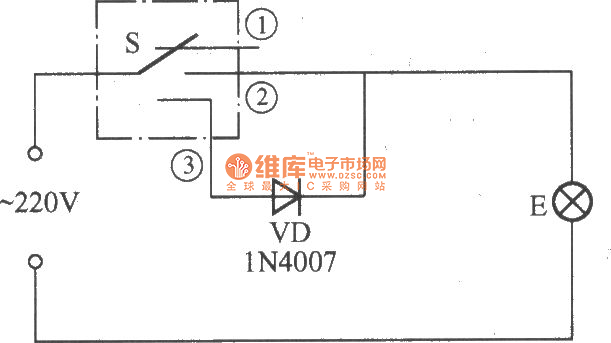
简易变光拉线开关电路-控制电路-其他控制电路图