您现在的位置是:主页 > 控制 > 其他控制电路图 >
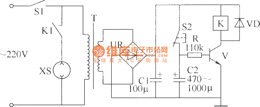
警报器控制键盘电路-控制电路-其他控制电路图
发布时间:2023-01-24 12:29:55所属栏目:其他控制电路图 已帮助人编辑作者:电路图知识网
4081
This switch will suit the Modular Burglar Alarm circuit. However, it also has other applICations. The Keypad must be the kind with a common terminal and a separate connection for each key. On a 12-key pad, look for 13 terminals. The matrix type with 7 terminals will NOT do. Choose the five keys you want as your code, and connect them to "A, B, C, D E". Wire the common to R1 and all the remaining keys to "F". Because your choice can include the non-numeric symbols, almost 100 000 different codes are available. The Alarm is set using the first four of your five chosen keys. When "A, B, C D" are pressed in the right order and within the time set by C1 and R2 (about 10 seconds), current through R11 switches Q6 on. The relay energizes, and then holds itself on by providing base current for Q6 through R12. The 12-volt output switches from the "off " to the "set " terminal, and the LED lights. To switch the Alarm off again it is necessary to press A, B, C, D E in the right order. The IC is a quad 2-input AND gate, a Cmos 4081. These gates only produce a high output when both inputs are high. Pressing "A" takes pin 1 high for a period of time set by C1 and R2. This "enables" gate 1, so that when "B" is pressed, the output at pin 3 will go high. This output does two jobs. It locks itself high using R3 and it enables gate 2 by taking pin 5 high. The remaining gates operate in the same way, each locking itself on through a resistor and enabling its successor. If the correct code is entered within the time allowed, pin 10 will switch Q5 on and so connect the base of Q6 to ground. This causes Q6 to switch off and the relay to drop out. Any keys not wired to "A, B, C, D or E " are connected to the base of Q4 by R9. Whenever one of these "wrong" keys is pressed, Q4 takes pin 1 low. This removes the "enable" from gate 1, and the code entry process fails. If C, D or E is pressed out of sequence, Q1, Q2 or Q3 will also take pin 1 low, with the same result. You can change the code by altering the keypad connections. If you make a mistake entering the code, just start again. If you need a more secure code you can use a bigger keypad with more "wrong" keys wired to "F". A 16-key pad gives over half a million different codes. All components are shown lying flat on the board; but some are actually mounted upright. The links are bare copper wires on the component side. Two of the links must be fitted before the IC.
Tags:
相关文章

其他控制电路图相关资讯
隧道二极管双稳态电路-控制电路-其他控制电路图
棉花湿度检测电路-其他控制电路图
简单的LED闪光灯电路图-其他控制电路图
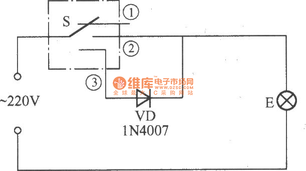
简易变光拉线开关电路-控制电路-其他控制电路图
采用功率开关集成电路的恒温控制电路-其他控制电路图
555简易恒温控制器电路-控制电路-其他控制电路图

采用晶体管的湿度控制电路-其他控制电路图

能驱动继电器的射极耦合单稳态电路-控制电路-其他控制电路图
1.5V低电源音频电平检测电路-其他控制电路图

峰值检知器电路(Peakdetector)-其他控制电路图
卫生间门控开关电路(四)-控制电路-其他控制电路图
采用UAA1016B集成电路的恒温控制电路-其他控制电路图
生物芯片扫描仪弱信号检测方法-其他控制电路图

5通道低功耗可编程传感器信号处理器AD7714和微处理器构成的隔离-其他控制电路图
液晶显示电子温度表电路-控制电路-其他控制电路图