您现在的位置是:主页 > 控制 > 其他控制电路图 >
CreatingaFastLoadTransient-其他控制电路图
发布时间:2023-01-24 03:23:29所属栏目:其他控制电路图 已帮助人编辑作者:电路图知识网
Creating a Fast Load Transient
Abstract: A simple circuit generates fast load transients for thorough testing of power supplies.
Many of Maxim's devices show a typical operating characteristic (TOC) graph with a very fast load transient. Our customers sometimes ask us how we create such fast changes in load. Although commercially available dynamic load boxes are capable of supplying transients, they do not provide the fast rise times and fall times necessary for an attractive-looking TOC.
To obtain fast load transients, we combine a power MOSFET and a couple of resistors right src="/data/attachment/portal/201007/ET29203201007211251151.gif">
Figure 1. Component connections.
Determining the value of R1 and selecting M1 depend src="/data/attachment/portal/201007/ET29203201007211251152.gif">
Figure 2. The MAX8654 load transient response.
Figure 3. Load transient response setup.
To achieve the best performance, keep the signal generator's duty cycle to 10% to reduce self-heating. Also, some converters are capable of supplying more than 25W, which is sufficient to cause minor injury or destroy the components if operated above 10% duty cycle.
The physical location of the components is critical for best performance. Usually they have to be cobbled onto an existing PC board. Keep both the MOSFET and R1 as close to the DUT's output capacitor as possible. Make the conductors as wide and short as you can.
Measurement of the DUT output should be done directly across the output capacitor. If the device is insensitive to 1000pF loading, use a 1X scope probe. The 1X probe provides the highest signal-to-noise ratio to the oscilloscope.
Whatever probe is used, though, make sure to have the ground lead as close to zero length as possible. Ideally, a scope-probe jack connected directly to ground and the output works very well. Any high-speed edge to be displayed on the scope is subject to this criterion, not just transient response.
Tags:
相关文章

其他控制电路图相关资讯
采用UAA1016B集成电路的恒温控制电路-其他控制电路图
生物芯片扫描仪弱信号检测方法-其他控制电路图
采用功率开关集成电路的恒温控制电路-其他控制电路图

能驱动继电器的射极耦合单稳态电路-控制电路-其他控制电路图

5通道低功耗可编程传感器信号处理器AD7714和微处理器构成的隔离-其他控制电路图
1.5V低电源音频电平检测电路-其他控制电路图
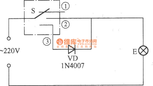
简易变光拉线开关电路-控制电路-其他控制电路图

峰值检知器电路(Peakdetector)-其他控制电路图
液晶显示电子温度表电路-控制电路-其他控制电路图

采用晶体管的湿度控制电路-其他控制电路图
棉花湿度检测电路-其他控制电路图
卫生间门控开关电路(四)-控制电路-其他控制电路图
简单的LED闪光灯电路图-其他控制电路图
隧道二极管双稳态电路-控制电路-其他控制电路图
555简易恒温控制器电路-控制电路-其他控制电路图