您现在的位置是:主页 > 光电 > 其他光电实用电路图 >
电源内阻:扼杀DC-DC转换效率的元凶(SourceResistance:TheEfficiencyKillerinDC...-其他光电实用电路图
发布时间:2023-03-27 17:22:38所属栏目:其他光电实用电路图 已帮助人编辑作者:电路图知识网
电源内阻:扼杀DC-DC转换效率的元凶
Abstract: DC-DC converters, common in battery-driven, portable, and other high-efficiency systems, can deliver efficiencies greater than 95% while boosting, reducing, or inverting supply voltages. Resistance in the power source is src="/data/attachment/portal/201007/ET29214201007211251201.gif">
Figure 1. A regulated power-distribution system has three basic sections.
Calculation and measurement of the source efficiency is very simple. EFFSOURCE equals (power delivered to the regulator)/(power provided by VPS) multiplied by 100%:
Assuming that the regulator draws a negligible amount of current when unloaded, you can measure source efficiency as the ratio of VIN with the regulator at full load to VIN with the regulator unloaded.
The regulator (DC-DC converter) consists of a controller IC and associated discrete components. Its characterization is described in the manufacturer's data sheet. Efficiency for the DC-DC converter (EFFDCDC) equals (power delivered by the converter)/(power delivered to the converter) multiplied by 100%:
As specified by the manufacturer, this efficiency is a function of input voltage, output voltage, and output load current. It's not unusual for the efficiency to vary no more than a few percent over a load current range exceeding two orders of magnitude. Because the output voltage is fixed, we can say the efficiency varies src="/data/attachment/portal/201007/ET29214201007211251204.gif">
This discussion treats the DC-DC converter as a twoport black box. For those interested in the nuances of DC-DC converter design, see References 1-3. The load includes the device to be driven and all dissipative elements in series with it, such as PC-trace resistance, contact resistance, cable resistance, etc. Because the DC-DC converter's output resistance is included in the manufacturer's data sheet, that quantity is specifically excluded. Load efficiency (EFFLOAD) equals (power delivered to the load)/(power delivered by the DC-DC converter) multiplied by 100%:
The key to optimum system designs is in analyzing and understanding the interaction between the DC-DC converter and its source. To do this we first define an ideal converter, then calculate the source efficiency, then test our assumptions against measured data from a representative DC-DC converterµin this case, the MAX1626 buck regulator.
An ideal DC-DC converter would have 100% efficiency, operate over arbitrary input- and output-voltage ranges, and supply arbitrary currents to the load. It would also be arbitrarily small and available for free! For this analysis, however, we assume src="/data/attachment/portal/201007/ET29214201007211251206.gif">
For a given load, this condition implies that the input current-voltage (I-V) curve is hyperbolic and exhibits a negative differential-resistance characteristic over its full range (Figure 2). This plot presents I-V curves for the DC-DC converter as a function of increasing input power. For real systems with dynamic loads, these curves are also dynamic. That is, the power curve moves farther from the origin as the load demands more current. Considering a regulator from the input port instead of the output port is an unusual point of view. After all, regulators are designed to provide a constant-voltage (sometimes constant-current) output. Their specifications predominantly describe the output characteristics (output-voltage range, output-current range, output ripple, transient response, etc.). The input, however, displays a curious property: within its operating range it acts as a constantpower load (Reference 4). Constant-power loads are useful in the design of battery testers, among other tasks.
Figure 2. These hyperbolas represent constant-power input characteristics for a DC-DC converter.
We now have enough information to calculate the source's power dissipation and therefore its efficiency. Because the open-circuit value of source voltage (VPS) is given, we need src="/data/attachment/portal/201007/ET29214201007211251208.gif">
IIN can also be solved in terms of VPS, VIN, and RS:
Equate the expressions from equations [6] and [7] and solve for VIN:
To understand their implications, it is very instructive to visualize equations [6] and [7] graphically (Figure 3). The resistor load line is a plot of all possible solutions of equation [7], and the DC-DC I-V curve is a plot of all possible solutions of equation [6]. The intersections of these curves, representing solutions to the pair of simultaneous equations, define stable voltages and currents at the DC-DC converter's input. Because the DC-DC curve represents constant input power, (VIN+)(IIN+) = (VIN-) (IIN-). (The + and - suffixes refer to the two solutions predicted by equation [8], and correspond to the ± signs in the numerator.)
It's easy to get lost in the equations, and therein lies the value of the load-line analysis plot of Figure 3. Note, for example, that if the series resistance (RS) equals zero, the resistor load-line slope becomes infinite. The load line would then be a vertical line passing through VPS. At this point VIN+ = VPS and the efficiency would be 100%. As RS increases from 0Ω, the load line continues to pass through VPS but leans more and more to the left. Concurrently, VIN+ and VIN- converge src="/data/attachment/portal/201007/ET292142010072112512012.gif">
Figure 4. A standard DC-DC converter circuit illustrates the ideas of Figure 3. 
Figure 5. Above VMIN, the MAX1626 input I-V characteristic closely matches that of a 90%-efficient ideal device.
When VIN exceeds VL, the input current climbs toward a maximum that occurs when VOUT first reaches the preset output voltage (3.3V). The corresponding input voltage (VMIN) is the minimum required by the DC-DC converter to produce the preset output voltage. For VIN > VMIN, the constant-power curve for 90% efficiency closely matches the MAX1626 input curve. Variations from the ideal are caused primarily by small variations in DC-DC converter efficiency as a function of its input voltage.
The power-supply designer must also guarantee that the DC-DC converter never becomes bistable. Bistability is possible in systems for which the load line intersects the DC-DC converter curve at or below VMIN/IMAX (Figure 6).
Figure 6. A closer look at the intersection points indicates a possibility of bistable and even tristable operation.
Depending src="/data/attachment/portal/201007/ET292142010072112512015.gif"> The source resistance (RS) should always be smaller than RBISTABLE. If this rule is broken, you risk highly inefficient operation or a complete shutdown of the DC-DC converter.
It might be helpful to plot, for an actual system, the relationship shown in equation [9] between source efficiency and source resistance (Figure 7). Assume the following conditions:
Figure 7. This plot of source efficiency vs. source resistance indicates multiple values of efficiency for a given RS.
VPS = 10V Open-circuit power-supply voltage
VMIN = 2V Minimum input voltage that ensures proper operation
PIN = 50W Power to the DC-DC converter's input (POUT/EFFDCDC).
Using equation [12], RBISTABLE can be calculated as 0.320Ω. Subsequently, a plot of equation [9] shows that source efficiency drops as RS increases, losing 20% at RS = RBISTABLE. Note: this result cannot be generalized. You must perform the calculations for each application. src="/data/attachment/portal/201007/ET292142010072112512017.gif">
Therefore,
A 5V/10A power supply with 1% load regulation, for example, would have only 5.0mΩ of output resistance- not much for a 10A load.
It's useful to know how much source resistance (RS) can be tolerated and how this parameter affects system efficiency. RS must be less than RBISTABLE, as stated earlier, but how much lower should it be? To answer this question, solve equation [9] for RS in terms of EFFSOURCE, for EFFSOURCE values of 95%, 90%, and 85%. RS95 is the RS value that yields a 95% source efficiency for the given input and output conditions. Consider the following four example applications using common DC-DC converter systems.
Example 1 derives 3.3V from 5V with a load current of 2A. For 95% source efficiency, be careful to keep the resistance between the 5V source and the DC-DC converter's input well under 162m½. Notice that RS90 = RBISTABLE, by coincidence. This value of RS90 also implies that the efficiency could as easily be 10% as 90%! Note that system efficiency (as opposed to source efficiency) is the product of source efficiency, DC-DC converter efficiency, and load efficiency.
Example 1. Application Using a MAX797 or MAX1653 DC-DC Converter (IOUT = 2A) VPSVOUTIOUTVMINEFFDCDCPOUTRBISTABLERS95RS90RS855V3.3V2A4.5V90%6.6W0.307Ω0.162Ω0.307Ω0.435Ω
Example 2 is similar to Example 1 except for outputcurrent capability (20A vs. 2A). Notice that the seriesresistance requirement for 95% source efficiency is 10 times lower (16mΩ vs. 162mΩ). To achieve this low resistance, use 2oz. copper PC traces.
Example 2. Application Using a MAX797 or MAX1653 DC-DC Converter (IOUT = 20A) VPSVOUTIOUTVMINEFFDCDCPOUTRBISTABLERS95RS90RS855V3.3V20A4.5V90%66W0.031Ω0.016Ω0.031Ω0.043Ω
Example 3 derives 1.6V at 5A from a source voltage of 4.5V (i.e., 5V-10%). The system requirement of 111mΩ for RS95 can be met, but not easily.
Example 3. Application Using a MAX1710 DC-DC Converter with Separate +5V Supply (VPS = 4.5V) VPSVOUTIOUTVMINEFFDCDCPOUTRBISTABLERS95RS90RS854.5V1.6V5A2.5V92%8W0.575Ω0.111Ω0.210Ω0.297Ω
Example 4 is the same as Example 3, but with higher supply voltage (VPS = 15V instead of 4.5V). Notice the useful trade-off: a substantial increase in the difference between input and output voltages has caused an efficiency drop for the DC-DC converter alone, but the overall system efficiency is improved. RS is no longer an issue because the large RS95 value (>1Ω) is easily met. A system with an input filter and long input lines, for example, can maintain a source efficiency of 95% or more without special attention to line widths and connector resistances.
Example 4. Application Using a MAX1710 DC-DC Converter with Separate +5V Supply (VPS = 15V) VPSVOUTIOUTVMINEFFDCDCPOUTRBISTABLERS95RS90RS8515V1.6V5A2.5V86%8W3.359Ω1.149Ω2.177Ω3.084Ω
When looking at DC-DC converter specifications, it is tempting to maximize efficiency by setting the supply voltage as close to the output voltage as possible. This strategy, however, can increase costs by placing unnecessary limitations on elements such as the wiring, connectors, and trace layout. System efficiency may even suffer. The analytic tools presented in this article should make such power-system trade-offs more intuitive and obvious.
References- Erickson, Robert W. Fundamentals of Power Electronics. Chapman and Hall, 1997.
- Lenk, Ron. Practical Design of Power Supplies. IEEE Press McGraw Hill, 1998.
- Gottlieb, Irving M. Power Supplies, Switching Regulators, Inverters and Converters. Second Edition, TAB Books, 1994.
- Wettroth, John. "Controller Provides Constant Power Load." EDN, March 14, 1997.
Tags:
相关文章


其他光电实用电路图相关资讯
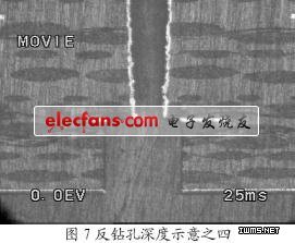
微波多层板反钻孔之金属化孔互连-其他光电实用电路图
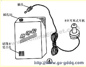
用分立元件制作的耳聋助听器-其他光电实用电路图
庭院太阳能照明灯电路-其他光电实用电路图
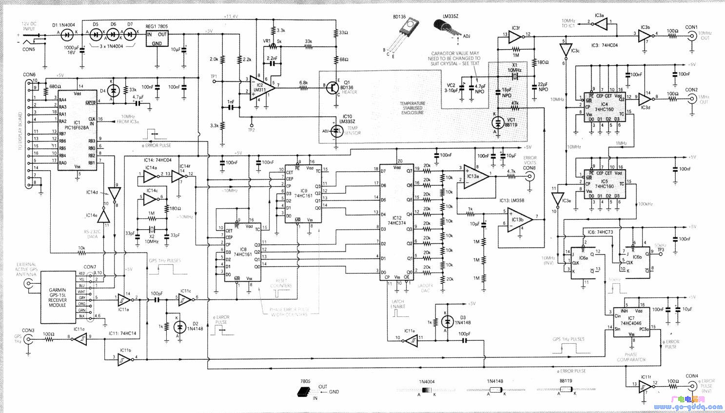
基于定位系统基准频率源的设计与制作-其他光电实用电路图
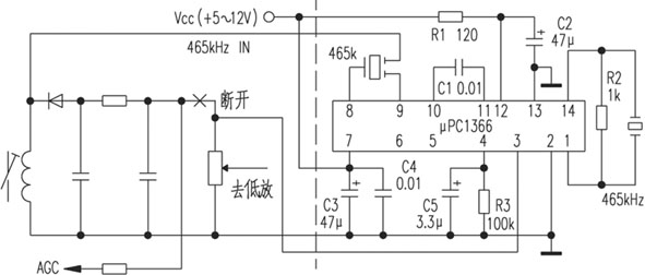
用μPC1366提高收音机灵敏度-其他光电实用电路图
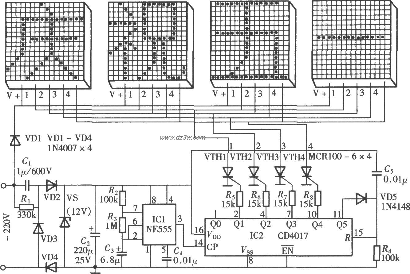
由NE555、CD4017组成的节-其他光电实用电路图
对讲机发射功率测试笔的制作-其他光电实用电路图
9800系列UHF发射单元的制作方法-其他光电实用电路图
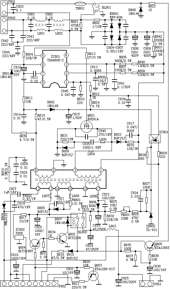
采用TDA4605-2制作的开关电源-其他光电实用电路图
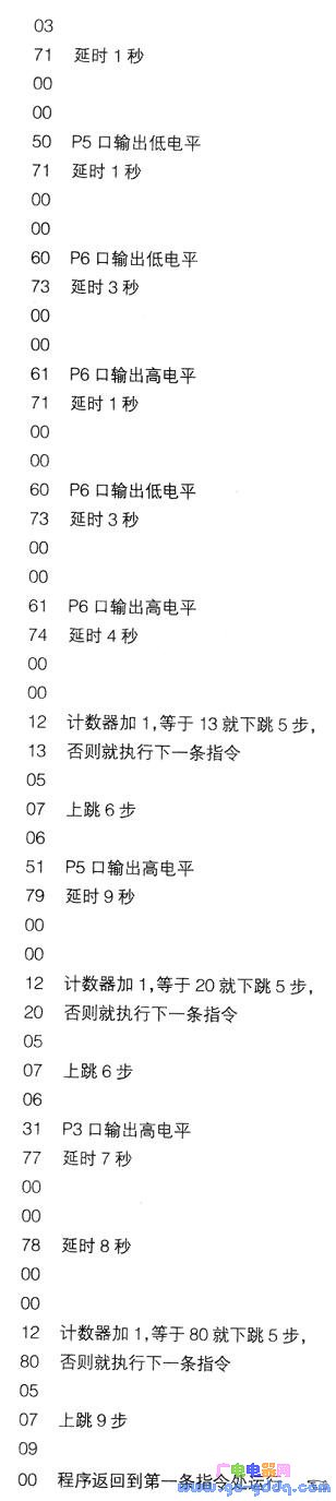
用PROG-110设计制作的多媒体投影机自动控制器-其他光电实用电路图

选择性去桥连技术提高焊接成品率-其他光电实用电路图

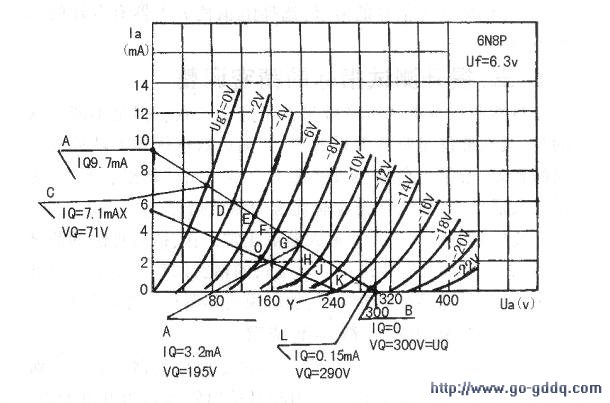
用6N7P电子管制作的单端功率放大器-其他光电实用电路图
选频声控开关电路设计与分析-其他光电实用电路图
电子扩音机安装后的电压检测与调整-其他光电实用电路图
卡拉OK人声增效电路-其他光电实用电路图