您现在的位置是:主页 > 光电 > 其他光电实用电路图 >
DualComparatorFormsTemperature-CompensatedProximityDetector-其他光电实用电路图
发布时间:2022-11-05 11:38:40所属栏目:其他光电实用电路图 已帮助人编辑作者:电路图知识网
Dual Comparator Forms Temperature-Compensated Proximity Detector
Abstract: Simple comparator and op amp circuit forms a temperature-compensated proximity detector.
In the proximity detector shown in Figure 1, a 4-inch-square piece of copper-plated PC board serves as an antenna that forms src="/data/attachment/portal/201007/ET34468201007230651241.gif">
Figure 1. This proximity detector lights the LED when a person approaches the antenna plate within a threshold set by the potentiometer.
The method for transforming this proximity distance into a proportional voltage is illustrated by a simplified circuit that lacks temperature compensation (Figure 2). Transitions of the input square wave apply directly to the lower input of the exclusive-OR (XOR) gate, but are delayed 0.693(R1)(C1) seconds before being reconstructed by the comparator and applied to the upper input. R4 and C2 filter the resulting XOR output to produce a voltage proportional to distance.
Figure 2. This circuit, uncompensated for temperature, illustrates the principle of capacitance-to-voltage conversion.
The XOR output's duty cycle is proportional to the sum of R1 + C1 delay plus comparator propagation delay, so a small variation in comparator delay can mask small changes in antenna capacitance. The Figure 1 circuit overcomes this limitation with a dual comparator (IC1). Passing the XOR inputs through nearly identical comparators largely nullifies the effect of offset voltage, drift, and propagation delay through the comparators.
Figure 1's delay capacitance consists of a 33pF capacitor (C1) in parallel with 15pF (6 inches of coaxial cable at 30pF per foot) and the 4-inch-square antenna plate. It charges to 5V via R5 during each positive half cycle of the input square wave. When no body is near the detector, this capacitance equals 48pF and produces a delay of 16.5ns at the upper XOR input. With a hand placed 6 inches from the detector, the capacitance rises to 50pF and produces a delay of 17.3ns, yielding a time difference of src="/data/attachment/portal/201007/ET34468201007230651243.gif">
Figure 3. The dual-comparator technique of Figure 1 offers much better temperature stability than that of the uncompensated circuit in Figure 2.
A similar idea appeared in the 2/16/98 issue of EDN.
MAX912/MAX913 pdf datasheet (TTL比较器)
Tags:
相关文章


其他光电实用电路图相关资讯
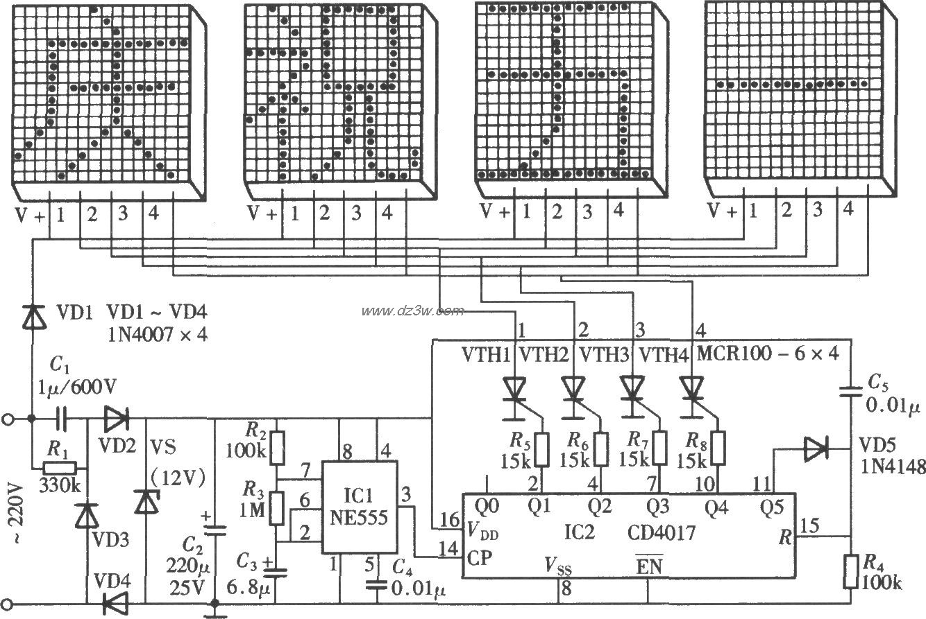
由NE555、CD4017组成的节-其他光电实用电路图

选择性去桥连技术提高焊接成品率-其他光电实用电路图
微波多层板反钻孔之金属化孔互连-其他光电实用电路图
电子扩音机安装后的电压检测与调整-其他光电实用电路图
庭院太阳能照明灯电路-其他光电实用电路图
用PROG-110设计制作的多媒体投影机自动控制器-其他光电实用电路图
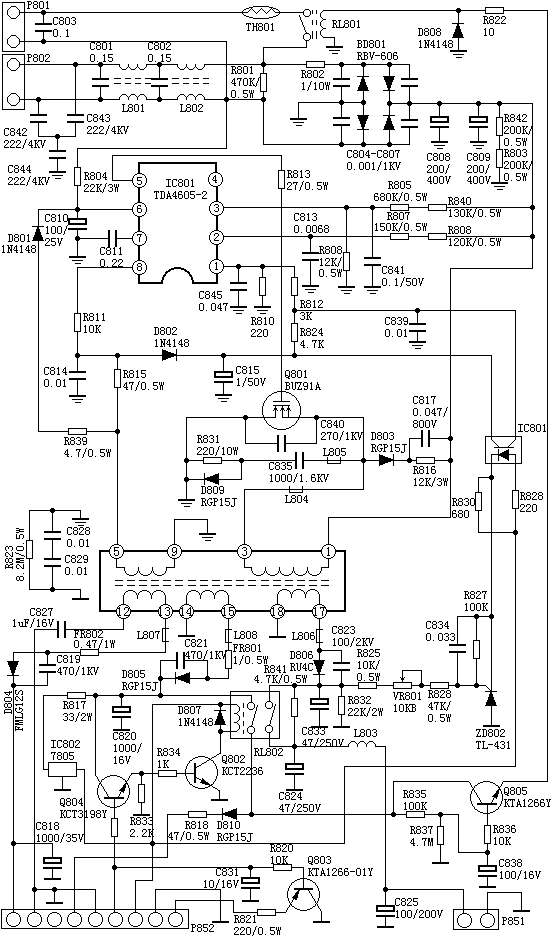
采用TDA4605-2制作的开关电源-其他光电实用电路图

用6N7P电子管制作的单端功率放大器-其他光电实用电路图
选频声控开关电路设计与分析-其他光电实用电路图
对讲机发射功率测试笔的制作-其他光电实用电路图
9800系列UHF发射单元的制作方法-其他光电实用电路图
卡拉OK人声增效电路-其他光电实用电路图
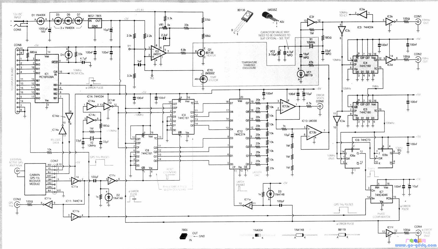
基于定位系统基准频率源的设计与制作-其他光电实用电路图
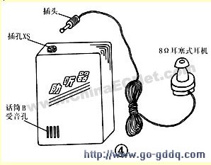
用分立元件制作的耳聋助听器-其他光电实用电路图
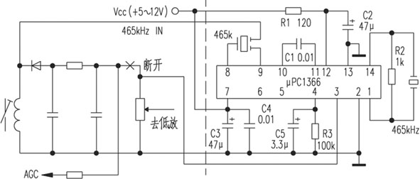
用μPC1366提高收音机灵敏度-其他光电实用电路图